Pump is a device or machine that is used to move liquids from one place to another through a piping medium by adding energy to the fluid being moved and continues over time.
Pump operates with the principle of making a difference in pressure between the inlet (suction) to the exit (discharge). In other words, the pump function convert mechanical power from a power source (driving) into kinetic energy (speed), which is useful to energy in a fluid and overcome the barriers that exist throughout the drainage.
Centrifugal pumps
One type of non-positive displacement pump is a centrifugal pump that works to change the principle of kinetic energy (speed) into potential energy fluid (dynamic) through a rotating impeller in the casing.
In accordance with the data obtained, the reboiler pump debutanizer in Hidrokracking Unibon using centrifugal pumps single - stage double suction.
Classification of Centrifugal Pumps
Centrifugal pumps can be classified, based on:
1 Capacity:
Low capacity <20 m3 / h
Medium capacity 20 -: - 60 m3 / h
High capacity> 60 m3 / h
2 Pressure Discharge:
Low pressure <5 kg / cm 2
Medium pressure 5 -: - 50 Kg / cm 2
High pressure> 50 Kg / cm 2
3 Number / Composition Impeller and Level:
Single stage: Consists of one impeller and the casing
Multi stage: Consists of several series of impellers arranged in a casing.
Multi Impeller: Consists of several impellers are arranged in parallel in a single casing.
Multi Impeller â € "Multi-stage: The combination of multi-stage and multi-impeller.
4 Position Axis:
upright shaft
horizontal shaft
5. Total Suction:
single Suction
Double Suction
6 The direction of flow out of the impeller:
radial flow
Axial flow
Mixed fllow
Wednesday, September 3, 2014
Major parts of the Centrifugal Pump
In general, the main parts of a centrifugal pump can be seen sepert following picture:

Casing Centrifugal Pump
A. Stuffing Box
Stuffing Box serves to prevent leaks in the area where the shaft penetrates the pump casing.
B. Packing
Used to prevent and reduce the leakage of fluid from the pump casing through the shaft. Usually made of asbestos or Teflon.
C. Shaft (shaft)
Serves to continue the shaft torque from the drive during operation and the seat of the impeller and other rotating parts.
D. Shaft sleeve
Shaft sleeve serves to protect the shaft from erosion, corrosion and wear at the stuffing box. In the multi-stage pump may be a joint leakage, and interstage internal bearing or distance sleever.
E. Vane
Blades of the impeller as the passage of fluid on the impeller.
F. Casing
Is the outermost part of the pump that serves as a protective element rotates, the seat of the diffusor (guide vane), inlet and outlet nozzles as well as providing the direction of flow of the impeller and convert energy into dynamic energy fluid velocity (single stage).
G. Eye of Impeller
The side entrance to the direction of the suction impeller.
H. Impeller
Impeller is used to convert the mechanical energy of the pump energy into the fluid being pumped speed continuously, so that the liquid on the suction side is continuously going in to fill the void caused by the displacement of the fluid before entering.
I. Wearing Ring
Wearing the ring serves to minimize fluid leakage past the front of the impeller and the back of the impeller, by minimizing the gap between the impeller casing.
J. Bearing
Beraing (pads) serves to rivet and the weight of the shaft in order to rotate, either radial load and axial load. Bearing also allows the shaft to rotate smoothly and stays in place, so that the frictional losses become small.
K. Casing
Is the outermost part of the pump that serves as a protective element rotates, the seat of the diffusor (guide vane), inlet and outlet nozzles as well as providing the direction of flow of the impeller and convert energy into dynamic energy fluid velocity (single stage).
Pump capacity
Pump capacity is the amount of fluid that can be moved by the pump per unit time. Expressed in units of volume per unit time, such as:
Barrels per day (BPD)
Gallons per minute (GPM)
Cubic meters per hour (m3 / hr)
Head Pump
Head pump is the energy per unit weight that should be provided to drain some liquid that was planned in accordance with the conditions of the pump installation, or pressure to drain some liquid, which is usually expressed in units of length.
According Bernauli equation, there are three kinds of head (energy) of the fluid flow system installations, namely, pressure energy, kinetic energy and potential energy
It can be expressed by the following formula:

 In different conditions like in the picture above, the Bernoulli equation is as follows:

1 Head Pressure
Head pressure is the difference in pressure head acting on the surface of the liquid at the press with head pressure acting on the surface of the liquid at the suction side.
Head pressure can be expressed by the formula:

2 Head Speed
Head speed is the difference between head velocity of liquid at the channel hit with a head speed of liquid at the suction channel.
Head velocity can be expressed by the formula:
3 Total Static Head
Total static head is the difference in height between the surface of the liquid at the surface of the press with liquid at the suction side.
Total static head can be expressed by the formula:
Z = Zd - Zs (5)
where:
Z: Head static total
Zd: Head of static on the side of the press
Zs: Head of static on the suction side
The +: If the surface of the liquid at the suction side of the pump is lower than the axis (Suction lift).
Signs -: If the surface of the liquid at the suction side is higher than the pump axis (Suction head).
4 Losses head (head loss)
Loss of energy per unit weight of fluid in the drainage of fluid in the piping system referred to as head loss (head loss).
Head loss consists of:
a. Major head loss (major losses)
Is the energy loss along the pipeline expressed by the formula:
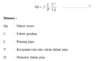
Price f (friction factor) obtained from the Moody diagram (Annexure - 6) as a function of Reynolds Number (Reynolds Number) and the relative roughness (Relative Roughness - Îμ / D), whose value can be seen in the graph (appendix) as a function of the nominal diameter of pipe and the pipe surface roughness (e) which depends on the type of pipe material.
While the magnitude of Reynolds Number can be calculated by the formula:
 b. Minor head loss (minor losses)
Is the head loss in fittings and valves located along the pipeline system. Can be searched by using the formula:

In calculating the loss in fittings and valves can use the table in Appendix 4 of this Magnitude declared losses in fittings and valves in sizes equivalent length of straight pipe.
c. total Losses
Total losses are total losses piping systems, namely:

According Bernauli equation, there are three kinds of head (energy) of the fluid flow system installations, namely, pressure energy, kinetic energy and potential energy
It can be expressed by the following formula:

Because energy is eternal, then the shape of the head (high press) can vary at different cross sections. But in fact there is always a loss of energy (losses).


1 Head Pressure
Head pressure is the difference in pressure head acting on the surface of the liquid at the press with head pressure acting on the surface of the liquid at the suction side.
Head pressure can be expressed by the formula:

Head speed is the difference between head velocity of liquid at the channel hit with a head speed of liquid at the suction channel.
Head velocity can be expressed by the formula:
Total static head is the difference in height between the surface of the liquid at the surface of the press with liquid at the suction side.
Total static head can be expressed by the formula:
Z = Zd - Zs (5)
where:
Z: Head static total
Zd: Head of static on the side of the press
Zs: Head of static on the suction side
The +: If the surface of the liquid at the suction side of the pump is lower than the axis (Suction lift).
Signs -: If the surface of the liquid at the suction side is higher than the pump axis (Suction head).
4 Losses head (head loss)
Loss of energy per unit weight of fluid in the drainage of fluid in the piping system referred to as head loss (head loss).
Head loss consists of:
a. Major head loss (major losses)
Is the energy loss along the pipeline expressed by the formula:

While the magnitude of Reynolds Number can be calculated by the formula:

Is the head loss in fittings and valves located along the pipeline system. Can be searched by using the formula:

c. total Losses
Total losses are total losses piping systems, namely:

power Pump
Pump power is the amount of energy per unit time or the speed of doing work.
There is some sense of power, namely:
1.Daya hydraulic (hydraulic horse power)
Hydraulic power (theoretical pump power) is the power needed to drain some liquid. This power can be calculated by the formula:

2 Power Pump Shaft (Break Horse Power)
To overcome the loss of the power needed by the real axis is greater than the hydraulic power.
The magnitude of the actual shaft power is equal to the efficiency of the pump or can be formulated as follows:

3 Power Mover (Driver)
Locomotion (driver) is divided by the power shaft mechanical efficiency (transmission efficiency). Can be calculated with the formula:

Pump efficiency
Efficiency is basically defined as the ratio between output and input or comparison between HHP pumps with pump BHP.
Highest efficiency price equal to the price of the pump efficiency is obtained from the manufacturer.
Pump efficiency is the multiplication of several effiaiensi, namely:

There is some sense of power, namely:
1.Daya hydraulic (hydraulic horse power)
Hydraulic power (theoretical pump power) is the power needed to drain some liquid. This power can be calculated by the formula:

To overcome the loss of the power needed by the real axis is greater than the hydraulic power.
The magnitude of the actual shaft power is equal to the efficiency of the pump or can be formulated as follows:

Locomotion (driver) is divided by the power shaft mechanical efficiency (transmission efficiency). Can be calculated with the formula:

Efficiency is basically defined as the ratio between output and input or comparison between HHP pumps with pump BHP.
Highest efficiency price equal to the price of the pump efficiency is obtained from the manufacturer.
Pump efficiency is the multiplication of several effiaiensi, namely:
Insulation System In Pump
Connecting my discussion of the pump on the previous posts. This time I will be a little review about the insulation system (Sealing System).
Selection of the right to a seal is very important to the success of the use of the pump. To get the best pump reliability, insulation must be appropriate choice between the environment and the type of seal used.
Fundamentals of Insulation (Seal)
There are two types of seals: static and dynamic.
Static seals are used where there is no movement going meetings between the two surfaces to be sealed. Gaskets and O-rings are a common example of a static seal.
Dynamic seals are used where there are surfaces that move relative to each other. Dynamic seals for example are used on a rotating shaft and delivers power through a wall of the tank (Figure 1), through the casing of the pump (Figure 2), or through the other rotating equipment such as filters or screens.


Typical examples of the use of the tools is insulation for sealing rotating shafts at the pump. To learn more about the function of this insulator, we must know in advance the basic knowledge of the pump.
In centrifugal pumps, the fluid entering into pump through the 'suction' at the center (eye) of the impeller is rotating. (Figures 3 and 4).


The function of packing is to control leakage, not to prevent all leakage. Because packing should always be lubricated and leak recommended to keep any lubrication is about 40 to 60 drops per minute.
Method of lubrication on the packing depends on liquid pumped ko0ndisi and also pressure on the stuffing box. When the stuffing box pressure above atmospheric pressure and the fluid is clean and not corrosive pressed, the fluid in the pump that is functioning as a gasket lubricant. (Figure 6).

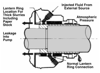
When the pressure in the stuffing box under atmospheric pressure, a lantern ring in pairs and lubricant injected into the stuffing box. (figure 7). A bypass pipe from the pump to the side of the press liaison lantern ring is generally used to provide a flow of liquid when the liquid is clean.

When the liquid being pumped is dirty or air particles, need to clean lubricating fluid injected from the outside through the lantern ring (figure 8). The flow of as much as 0.2 to 0.5 gpm faucet required and a regulator and flowmeter needs to be installed to get accurate flow. Lantern rings are usually mounted in the middle of the stuffing box, but for highly viscous liquids such as raw materials recommended paper is installed in the neck to avoid blockage of the stuffing box lantern ring.
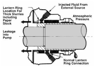
Packing house (glands) in Figure 5 to 8 is a type of 'quench gland'. Water, oil or other fluids can be injected into the gland to reduce heat shaft, it can minimize the heat transfer from the shaft to the bearing. Allow for this reason that the working temperature of the pump is higher than the design of temperature bearing and pelumas.Tipe 'quench gland' the same can be used to prevent the release of toxic or hazardous fluids out into the outside air around the pump. It is called 'smothering gland', by draining fluid from the outside and bring unwanted leakage into the trench or former liquid collection tank.
Selection of the right to a seal is very important to the success of the use of the pump. To get the best pump reliability, insulation must be appropriate choice between the environment and the type of seal used.
Fundamentals of Insulation (Seal)
There are two types of seals: static and dynamic.
Static seals are used where there is no movement going meetings between the two surfaces to be sealed. Gaskets and O-rings are a common example of a static seal.
Dynamic seals are used where there are surfaces that move relative to each other. Dynamic seals for example are used on a rotating shaft and delivers power through a wall of the tank (Figure 1), through the casing of the pump (Figure 2), or through the other rotating equipment such as filters or screens.

In centrifugal pumps, the fluid entering into pump through the 'suction' at the center (eye) of the impeller is rotating. (Figures 3 and 4).
At the time of the fan impeller rotates, they deliver the movement to include a product, which then leaves the impeller, collected in the pump housing (casing) and leaves the pump through pressure on the exit side (discharge) pump.
Discharge pressure will suppress some products down behind the impeller to the shaft, where he will try out all the rotating shaft. Pump manufacturers use a variety of techniques to reduce the pressure of the product to try out. Some common ways are:
The addition of a counterweight hole (hole balance) through the impeller to provide a way for the pressure that will come out through the suction side of the impeller.
The addition of the fan on the back side of the impeller (back pump-out vanes).
However, as long as there is no way to reduce this pressure completely, sealing equipment is absolutely necessary to restrict the release of the product. As baffle compression (packing) or mechanical sealing (mechanical seals).
Stuffing Box Packing
Setting the use of 'stuffing box' is shown in the figure below. It consists of:
5 ring packing.
A lantern ring is used to inject peluamas and or to dispose of liquid
A suppressor (gland) to hold the packing and keep the pressure needs tightening packing adapted to the conditions.

Method of lubrication on the packing depends on liquid pumped ko0ndisi and also pressure on the stuffing box. When the stuffing box pressure above atmospheric pressure and the fluid is clean and not corrosive pressed, the fluid in the pump that is functioning as a gasket lubricant. (Figure 6).

When the pressure in the stuffing box under atmospheric pressure, a lantern ring in pairs and lubricant injected into the stuffing box. (figure 7). A bypass pipe from the pump to the side of the press liaison lantern ring is generally used to provide a flow of liquid when the liquid is clean.

When the liquid being pumped is dirty or air particles, need to clean lubricating fluid injected from the outside through the lantern ring (figure 8). The flow of as much as 0.2 to 0.5 gpm faucet required and a regulator and flowmeter needs to be installed to get accurate flow. Lantern rings are usually mounted in the middle of the stuffing box, but for highly viscous liquids such as raw materials recommended paper is installed in the neck to avoid blockage of the stuffing box lantern ring.
Packing house (glands) in Figure 5 to 8 is a type of 'quench gland'. Water, oil or other fluids can be injected into the gland to reduce heat shaft, it can minimize the heat transfer from the shaft to the bearing. Allow for this reason that the working temperature of the pump is higher than the design of temperature bearing and pelumas.Tipe 'quench gland' the same can be used to prevent the release of toxic or hazardous fluids out into the outside air around the pump. It is called 'smothering gland', by draining fluid from the outside and bring unwanted leakage into the trench or former liquid collection tank.
Mechanical Seal
Definition
Mechanical Seals, freely translated, is a mechanical block maker. However, the translation becomes more difficult to understand and imagine if compared to the technical sense. Why? Because understanding the mechanical seal means so broad. Are all types of mechanical seals can be called with a mechanical seal? An O-ring mechanical seals, as well as Labyrinth Seal, but both are definitely not MechanicalSeal.

Mechanical seals are discussed on this site is a type of seals used in industrial grade pumps, agitators, mixers, chillers and all rotating equipment (rotating machinery).
For ease of understanding, then this site feel the need to declare the writing is the ideal mechanical seal Mechanical Seal and agreed in advance that the mechanical seal is essentially fall into the category seal. Seal will not be translated yet clarified its understanding through a series of examples.
Terminology
The most difficult for beginners is the understanding of the terms used in reference to the mechanical seal. For that let us equate perception advance over the following matters:
SHAFT is as / the shaft of a tool and a major part of rotating machines. Manual machines often use the word as shafts compared.
SHAFT SLEEVE is a bushing / sleeve-shaped adapter which is mounted on the shaft with the aim of protecting the shaft due to the tightening of the bolt / screw MechanicalSeal.
SEAL is a part / parts in a construction equipment / machinery that serves as a barrier to exit / entry of liquid, either the process fluid or lubricant. On a motorcycle or car repair shops often said rubber seals, seals-as crutches, oil-seal. Another analogy, try to imagine a tank. What would happen if the glass affixed to the glass without any glue / sealant?
Glue the glass after hardened, in these conditions is the seal. Seal can be agreed that refers to the notion of a function. Whatever the shape and material, if functioning to prevent leakage, then he called the Seal.
O-RING originally was referred to the circular rubber which serves as a Seal. The development of technology as a tool o-ring pengeblok secondary fluid (secondary sealing device) produces various types of o-rings based on the material. O-ring material, there are natural rubber, EPDM, Buna, Neoprene, Viton, Chemraz, Kalrez, Isolast to type Encapsulated O-Ring, where the o-ring wrapped with PTFE. Some are purely made from PTFE and is called the Wedge.
SEALFACE is the most important part, the first and most critical of a Mechanical Seal and a point to obstacle MAIN FLUID (primary sealing device) Made of Carbon or Silicone Carbide or Tungsten Carbide or ceramics or Ni-resist, with a series of mixing techniques. Surface material to meet each other (contact) is made so smooth up to the level of smoothness / flatness of the surface reaches 1-2 lightband.
Sealface Often referred to as the contact face. Seal faces means that there are 2 sealface. One silent and pump attached to the wall, and the other spins, attached to the shaft.
Which spins are usually made from softer material / soft. Can be a combination of carbon versus silicone carbide, carbon vs. ceramic, carbon vs. tungten carbide, silicone carbide vs. silicone carbide, silicone carbide vs. tungsten carbide.
After understanding the parts that make up the Mechanical Seal, Mechanical Seals can be followed that is a sealing device which is a combination of fused between sealface attached to the rotating shaft and stationary sealface and attached to the wall static casing / housing pump / tank / vessel / fan.
Sealface that of the rotating shaft is often referred to as the Rotary Face / Primary Ring. While Sealface dwelling or in a stationary condition is often referred to as StationaryFace / Mating Ring / Seat.

Thus the conclusion can be drawn definition of Mechanical Seal is a tool pengeblok liquids / gases on a rotating equipment, which consists of:
Two sealface that can wear out, where one stationary and one rotating, form the primary blocking point (primary sealing).
One or a group of o-ring / bellows / PTFE wedge which is a secondary blocking point (secondary sealing).
Pembeban mechanical tool to make sealface pressed together.
Metal accessories needed to complete the series Mechanical Seals.
How it Works Mechanical Seal
The main point made by two sealfaces blocking surface is very smooth and flat. Friction between the spinning motion of both minimizing the occurrence of leaks. One sealface round shaft rotates to follow, one more silent mounted directly on a wall called Glandplate.
Meterial two sealfaces it is usually different. That one is usually soft, usually carbon-graphite, the other is made of a harder material such as silicone-carbide.
The distinction between the material used in stationary and rotating sealface sealface aalah to prevent adhesion between the two sealfaces. In sealface are usually softer smaller end so often known as wear-nose (the tip that could run out or wear rubbed).

There are four (4) point sealing / blocking, which is also the point of blocking the leak paths if it fails.
Please see the picture above. The main blocking point (primary sealing) is on contactface, 2 pieces sealfaces meeting point, see Point A, Point B leakage path is blocked by an O-Ring, or V-Ring or Wedge (read: WED). While the leakage path at Point C and Point D, blocked with gaskets or O-Ring.
Point B, C & D is called the secondary sealing.
Mechanical Seals, freely translated, is a mechanical block maker. However, the translation becomes more difficult to understand and imagine if compared to the technical sense. Why? Because understanding the mechanical seal means so broad. Are all types of mechanical seals can be called with a mechanical seal? An O-ring mechanical seals, as well as Labyrinth Seal, but both are definitely not MechanicalSeal.
For ease of understanding, then this site feel the need to declare the writing is the ideal mechanical seal Mechanical Seal and agreed in advance that the mechanical seal is essentially fall into the category seal. Seal will not be translated yet clarified its understanding through a series of examples.
Terminology
The most difficult for beginners is the understanding of the terms used in reference to the mechanical seal. For that let us equate perception advance over the following matters:
SHAFT is as / the shaft of a tool and a major part of rotating machines. Manual machines often use the word as shafts compared.
SHAFT SLEEVE is a bushing / sleeve-shaped adapter which is mounted on the shaft with the aim of protecting the shaft due to the tightening of the bolt / screw MechanicalSeal.
SEAL is a part / parts in a construction equipment / machinery that serves as a barrier to exit / entry of liquid, either the process fluid or lubricant. On a motorcycle or car repair shops often said rubber seals, seals-as crutches, oil-seal. Another analogy, try to imagine a tank. What would happen if the glass affixed to the glass without any glue / sealant?
Glue the glass after hardened, in these conditions is the seal. Seal can be agreed that refers to the notion of a function. Whatever the shape and material, if functioning to prevent leakage, then he called the Seal.
O-RING originally was referred to the circular rubber which serves as a Seal. The development of technology as a tool o-ring pengeblok secondary fluid (secondary sealing device) produces various types of o-rings based on the material. O-ring material, there are natural rubber, EPDM, Buna, Neoprene, Viton, Chemraz, Kalrez, Isolast to type Encapsulated O-Ring, where the o-ring wrapped with PTFE. Some are purely made from PTFE and is called the Wedge.
SEALFACE is the most important part, the first and most critical of a Mechanical Seal and a point to obstacle MAIN FLUID (primary sealing device) Made of Carbon or Silicone Carbide or Tungsten Carbide or ceramics or Ni-resist, with a series of mixing techniques. Surface material to meet each other (contact) is made so smooth up to the level of smoothness / flatness of the surface reaches 1-2 lightband.
Sealface Often referred to as the contact face. Seal faces means that there are 2 sealface. One silent and pump attached to the wall, and the other spins, attached to the shaft.
Which spins are usually made from softer material / soft. Can be a combination of carbon versus silicone carbide, carbon vs. ceramic, carbon vs. tungten carbide, silicone carbide vs. silicone carbide, silicone carbide vs. tungsten carbide.
After understanding the parts that make up the Mechanical Seal, Mechanical Seals can be followed that is a sealing device which is a combination of fused between sealface attached to the rotating shaft and stationary sealface and attached to the wall static casing / housing pump / tank / vessel / fan.
Sealface that of the rotating shaft is often referred to as the Rotary Face / Primary Ring. While Sealface dwelling or in a stationary condition is often referred to as StationaryFace / Mating Ring / Seat.

Two sealface that can wear out, where one stationary and one rotating, form the primary blocking point (primary sealing).
One or a group of o-ring / bellows / PTFE wedge which is a secondary blocking point (secondary sealing).
Pembeban mechanical tool to make sealface pressed together.
Metal accessories needed to complete the series Mechanical Seals.
How it Works Mechanical Seal
The main point made by two sealfaces blocking surface is very smooth and flat. Friction between the spinning motion of both minimizing the occurrence of leaks. One sealface round shaft rotates to follow, one more silent mounted directly on a wall called Glandplate.
Meterial two sealfaces it is usually different. That one is usually soft, usually carbon-graphite, the other is made of a harder material such as silicone-carbide.
The distinction between the material used in stationary and rotating sealface sealface aalah to prevent adhesion between the two sealfaces. In sealface are usually softer smaller end so often known as wear-nose (the tip that could run out or wear rubbed).

Please see the picture above. The main blocking point (primary sealing) is on contactface, 2 pieces sealfaces meeting point, see Point A, Point B leakage path is blocked by an O-Ring, or V-Ring or Wedge (read: WED). While the leakage path at Point C and Point D, blocked with gaskets or O-Ring.
Point B, C & D is called the secondary sealing.
Subscribe to:
Posts (Atom)